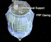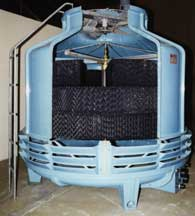
With our own technology, we have achieved energy conservation and noise reduction (LN-SLN-Model)
Fan blade contour, angle, air flow quantity, all these factors were taken into consideration in pursuit of and to achieve the lowest possible noise. At the same time, we use motor of, low output as well as low noise, and succeeded in superbly low noise and economical performance. Low noise fan is used on SLN Model as well. With its rationally designed fan blade contour, it generates big air flow quantity with low noise, without carryover. Fan motor operates with lower output than the conventional one and is very economical.
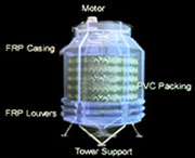
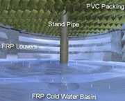
Free from rust, FRP finishing brings about uniform quality
Casing and water Basin are made of rigid FRP (Fiber glass Reinforced Polyester), eliminating corrosion which is the biggest enemy of cooling tower. It is light weight and superbly durable. Modeled with Aqua-Loop's originality, and it is uniform quality because
Highly efficient fills for heat exchange
The PVC (Polyester Vinyl Chloride) fill Aqua-Loop developed for counter flow cooling towers is flame resistant and has very high heat exchange performance. The specially combined material makes it durable and withstand; chemical reaction.
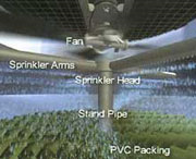
Aqua-Loop's unique sprinkler system (with eliminator to prevent carry - over), ensures maximum performance capability of fills
Sprinkler which automatically rotates at low water pressure gives least carry-over and uniform distribution or circulating water to the fills. It ensures maximum performance capability.
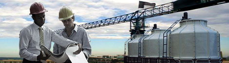
Cooling tower technology in the power industry
THERE HAVE BEEN a number of significant changes in the cooling tower technology associated with the power industry over the last 20 to 30 years. Innovations in cooling tower technology include new types of fill media and materials of construction, and hybrid tower changes. These changes were the result of a number factors, including technical advances, industry need, environmental regulation and competition in the cooling tower industry.
Historical perspective
In the early 1960s and 1970s the tower technology primarily employed consisted of wooden, cross-flow mechanical-draft towers were relatively inexpensive but had high operating and maintenance (O&M) costs. Concrete towers were used chemistry and O&M cost considerations. Even with higher O&M costs, mechanical-draft towers were used in certain applications, depending on water chemistry and O&M cost considerations. Even with higher O&M costs, mechanical-draft towers were often chosen over natural towers, due to the relatively low cost of installed generation (US$100/kW) and the associated energy penalties. The industrial boom during the 1970s and 1980s contributed to the demand for power generation. As the demand grew, so did the size of generating units (up to 500MW) and so did the cooling towers. Consequently, natural - draft towers (both cross flow and counter flow) because more popular during the 1970s and 1980s, especially with the increased emphasis on space considerations, pump head and reduced O&M costs. For a number of years, there was a misconception in some parts of the USA that natural -draft towers were not an appropriate technology, but this idea was dispelled by installations in the southeast USA. Even so, natural-draft towers were only really competitive on the larger generating units (up to 500 MW) with larger cooling water volumes. The oil embargo in the mid-1970s (which impacted on capital costs with double-digit inflation), together with the trend towards energy conservation and environmental protection. Low-cost installed generation became a thing of the past, focusing attention on efficient tower performance and O&M costs.
Fill-media trends
Counter -flow tower designs (both mechanical and natural draft) slowly became popular due to lower pumping heads and energy requirements and the use of film fills rather than splash-type fills. Initial film fill media included flat cement-asbestos boards (CAB). CAB fill was prone to delaminate and/or clog, resulting in loss of tower efficiency and the replacement of the tower fill. It eventually lost favour with the emergence of high-efficiency Polyvinyl Chloride (PVC) film-type fills in the late 1970s and early 1980s. PVC fill media was fabricated in modular fill packs, which helped reduced the overall time of construction (and labour costs). The initial high-efficiency PVC fill-packs were cross-fluted, which increased the surface (film) area and enhanced heat transfer. However, during the 1980s and 1990s, many of the towers with the PVC high-efficiency film fills began to plug and/or clog up due to bio-fouling and the deposition of suspended and dissolved solids. The cross-fluted fill designs were, unfortunately, inefficient water filters, which eventually led to plugged fill and loss of thermal performance. This phenomenon created an industry-wide need for anti-fouling fill designer or film fill designs that prohibited and / or mitigated fouling and plugged fill.
Anti-fouling fill
It should be noted that, while a none -fouling fill design has yet to be developed, numerous anti - fouling fill designs have been developed and used, with mixed success. An anti - fouling fill id one that will allow only a minor degree of initial fouling to occur and does not allow propagation or fouling / plugging for the operating life of the tower/fill. The anti - fouling fill designs used by Southern Company Services have been tested and approved in a long-term in-situ test program. Anti - fouling fill designs typically have straight flutes (with unobstructed paths through the fill pack) rather than cross-fluted in the high efficiency fills. Towers with anti-fouling fill designs usually require substantially more fill height than towers with high-efficiency fouling fill designs to achieve the same amount of cooling.
Drift eliminators
The use of PVC drift eliminators (Des) became popular in the 1970s to 1980s, due to reduced cost and higher efficiency for drift removal. Prior to the use of PVC, the earlier DE designs often included flat, wooden (redwood) states which had drift rates as high as 0.5 per cent (as tower flow). Initial PVC DE designs were basically wave-type or air-foil designs which greatly improved drift rates of < 0.1 per cent. With the emergence of PVC fill packs came the design of modular PVC DEs with drift rates of < 0.01 per cent. Continuing research and an emphasis on environmental emissions continued to drive the evolution of DE designs, some of which can now provide drift rates from 0.005 per cent to as low as 0.0005 per cent. Lower drift rates may be attainable, but current drift measurement technology may not be able to substance such claims.
Construction materials
Tower structures on generating units built in the early 1960s and 1970s primarily consisted of redwood and / or Douglas Fir timber. With the industrial boom in the 1970s came the use of fiberglass components such as fan stacks and blades. The larger generating units (fossil and nuclear) in the 1970s and 1980s required substantial space for the large mechanical draft towers (up to 30 to 40 cells). Tower orientation and plume issues often resulted in the selection and use of concrete natural-draft towers to elevate the plume - this also required less space. In the late 1970s and mid 1980s several redwood mechanical-drift towers suffered structural failures and damage due to design problems. This required substantial modification and refurbishment of existing towers and the design of new towers for enhanced structural integrity. By the late 1980s, the reduced available of redwood eventually drove up its cost, and the high maintenance cost of wooden concrete, steel and fiberglass. The evolution of fiberglass technology eventually increased awareness of pultruded fiberglass components in the cooling tower industry.
Pultruded fiberglass
Pultruded fiberglass components are lightweight and stronger than their wooden counterparts. They are also generally impervious to water corrosion. Consequently, in the late 1980s and early 1990s, Southern Company Services investigated and pursued the use of pultruded fiberglass components. This resulted in the construction of the largest fiberglass cooling tower in the utility industry at that time. Since then, the use of pultruded fiberglass components in the structural design of cooling towers has boomed in the utility industry and elsewhere. But this has led to concern over other technical issues, since fiberglass does not have the same characteristics as wood. These issues continue to be paramount in the development of appropriate codes and standards by the Cooling Technology Institute.
Environmental regulation
The power industry has seen significant changes in cooling tower and system designs as a result of environmental regulation, technological advances and competition in the power industry. Because of these changes, there has been an increased awareness and recognition that cooling tower and system performance can either make or break plant efficiency (thus impacting generation capability and ROI).